|
|
Post by elmer on Jul 18, 2018 18:57:30 GMT
If you want using your own vsync/hsync handler you have a system included in the CDROM handler one to do that. You can use it like that: Hmmmm ... isn't punch writing in assembly? I seem to remember that from the PCEFX forums. He also wanted to stop the BIOS's from writing the BXR & BYR registers on an RCR interrupt. So, doing it with the System Card functions ... sei
stw #my_vsync_hndl,vsync_hook ; Set VSYNC handler.
stw #my_hsync_hndl,hsync_hook ; Set HSYNC handler.
cli
lda #%11010000 ; Enable our handlers
tsb <irq_m ; & stop BIOS RCR code.
jsr ex_rcron ; Enable RCR interrupt.
You can progressively take more control of things if you use some of the other bits in irq_m.  |
|
Deleted
Deleted Member
Posts: 0
|
Post by Deleted on Jul 18, 2018 19:40:08 GMT
That's the meaning of "nop rcr irq"? Sometimes I wonder if Hudson sold a hintbook for their manuals via mail order.
edit: to clarify, I was simply setting IRQ_M to "0000 0010" to take over the IRQ interrupt and sort out who triggered it myself through the status flags. Might still keep doing that after what elmer said about resolution and timings.
edit2: I just got reminded of when I was expecting the vblank interrupt to fire through the NMI vector just like the NES and not having my code work at all. Took a while until I figured out that the NMI pin isn't connected to anything on the PCE. Good times.
|
|
touko
Punkic Cyborg

Posts: 106
|
Post by touko on Jul 19, 2018 6:46:29 GMT
Of course, the next useful irq to handle manually is the timer for example .
using your own handler like posted before, bypasses the Huc handler(it also works for hucard,and it's how the huc handler works too),so it shouldn't change BXR/BYR anymore but some functions shouldn't work too.
It's not enough, because even if you set the good bit in irq_m the system handler is always the first to take the irq when firing because he's hard coded in ROM .
Then it tests some bits of irq_m and launch the user one if corresponding bits are set .
It jsr to:
vsync_hook
hsync_hook
timer_jmp (only with CDsystem)
This is why you also must initialise those vectors with the addresses of your own functions,and not only the irq_m bits,else it don't works correctly.
I think your problem is not the bios handler but huc handler, and not having an initialised hsync_hook/vsync_hook(the both are important here) by your own handler, the bios still launch the huc's one,and so, still modifying the BXR/BYR for his scroll functions .
|
|
Deleted
Deleted Member
Posts: 0
|
Post by Deleted on Jul 19, 2018 16:13:40 GMT
Yes Touko, I'm using ex_setvec to write the address of my handler  that's not the issue I was having. Guess I have to improve my communication skills. I'll post the full source when I get home. |
|
touko
Punkic Cyborg
Posts: 106
|
Post by touko on Jul 19, 2018 17:59:21 GMT
Yes Touko, I'm using ex_setvec to write the address of my handler that's not the issue I was having. Guess I have to improve my communication skills. No problem punch ;-) yeah it should be better  |
|
Deleted
Deleted Member
Posts: 0
|
Post by Deleted on Jul 19, 2018 23:52:35 GMT
I mean I'm not doing anything out of the ordinary with my code but here it is anyway. Keep in mind that I really didn't find any time to work on this for the last few days so it should be exactly as it was when I made my large post with the "lines" screenshot.
;PC Engine Bike game
;By Punch

VRAM_TILEOFFSET 	= $40 ;First valid character code is #40, each char is 16 vram words.
VRAM_TILEADDRESS 	= $0800
MAP_OFFSET			= $0000	 ;Tilemap is located at VRAM address $0
SG_OFFSET			= $4000
SAT_OFFSET			= $7F00  ;SAT copy located at last 256 VRAM words.
BSS_OFFSET 			= $2700 	;RAM starts at $2648 with Syscard3 BIOS
BANK_OFFSET 		= 1 	;Since the PCE version is CD, bank 0 is CDROM IPL: sectors 0~3

INITIAL_X = 0
INITIAL_Y = 0
REDLINE = 127
GREENLINE = 24

 .ZP
SCANLINE		.ds 1 ;Line to trigger RCR interrupt
SCANLINE_OFFSET .ds 1 ;Either 0 or 16
 .BSS


	.include "CDROM\CD_Sector0.asm"
	.include "CDROM_DataLayout.asm"

 .CODE
 .bank 1
 .org $4000

RESET:
	.include "init.asm"

Initialized:
	LDA #01
	LDY #HIGH(IRQ1)
	LDX #LOW(IRQ1)
	JSR ex_setvec

	;Right nibble enables interrupt vector passthrough
	;If IRQ1 flag is off you can have the BIOS sort out
	;if the IRQ1 was triggered by VBlank or RCR then
	;give control to pseudo interrupt vectors (left nibble flags)

	;LDA #%0101_0000  Control to pseudo interrupts
	LDA  #%0000_0010 ;Real IRQ1 control
	STA irq_m

	;If we don't run this routine the RCR_Int pseudovector
	;we set up will never run, but it seems like
	;the BIOS executes its own RCR routine before handing over
	;control to us, setting X/Y values defined at EX_SETRCR.
	;Of course this can be bypassed by just receiving the real
	;IRQ1 interrupt instead of doing this.
	;JSR ex_rcron

	;Let's turn on by ourselves the hardware interrupt flags just in case.
	ST0 #5
	ST1 #%1100_1100

MainLoop:
	;This adds a significant delay to RCR IRQ1 interrupts
	;so it's better not to wait for new frames this way.
	;JSR ex_vsync

	JMP MainLoop

;We call this if we suspect the RCR functionality
;triggered the IRQ1 interrupt.
RCR_Int:
	INC <$10
	;RTS
	;This is supposed to make the green line appear
	;immediately below the red line.
	ST0 #8
	ST1 #GREENLINE - 1
	ST2 #0
.end
	RTS

IRQ1:
	PHA
	PHX
	PHY

.identifyYourself:
	;Checks if the IRQ generated is from RCR
	LDA $0000
	AND #%0000_0100
	BEQ .VBlank

.RCR
	JSR RCR_Int
	JMP .end

.VBlank
	;Register the scanline with the redline
	;for an interrupt
	LDA #REDLINE + 64
	ST0 #06
	STA $0002
	STZ $0003

.endb
	;Let's reset the video display too.
	;Capturing IRQ1 from the BIOS means that the background scroll
	;is no longer controlled automatically with bg_x1 and bg_y1!
	ST0 #8
	ST1 #INITIAL_Y
	ST2 #0
	ST0 #7
	ST1 #INITIAL_X
	ST2 #0

.end
	PLY
	PLX
	PLA
	RTI

 .bank 2
 .org $6000
 .db "TESTESTSETSTSET"

test_bg:  .incbin "ART\BG2_BAT.bin"
test_pal: .incbin "ART\BG2_PAL.bin"
|
|
|
|
Post by theoldman on Jul 20, 2018 2:05:11 GMT
Stipid question (admittedly)....
You do
" ;Let's turn on by ourselves the hardware interrupt flags just in case.
ST0 #5
ST1 #%1100_1100
" Where's the corresponding ST2 ? Aren't the registers latched when the high byte is written?
|
|
Deleted
Deleted Member
Posts: 0
|
Post by Deleted on Jul 20, 2018 2:22:00 GMT
Stipid question (admittedly)....
You do
" ;Let's turn on by ourselves the hardware interrupt flags just in case.
ST0 #5
ST1 #%1100_1100
" Where's the corresponding ST2 ? Aren't the registers latched when the high byte is written?
I seem to have read somewhere that only register 2 (the VRAM read/write access register) latches the least significant byte, which makes sense because in this specific register you need to make the address autoincrement work somehow.
I think that all other registers receive the value instantly without needing to have the most significant byte written. Not that it matters since I was just being lazy, in a real program I'd have to write something to the high byte (edit: more specifically the autoincrement mode bits) because sooner or later I'd have to access VRAM (outside of the BIOS easy routines that is).
|
|
|
|
Post by elmer on Jul 20, 2018 6:26:40 GMT
 The -1 offset (the green line being positioned exactly on top of the red line instead of being immediately below it) is probably explained by how my program isn't rendering the first line (another solid green line) on the screenshot. Emulation? Default System Card 3 screen config doesn't render the first line? I don't know but I'm pretty sure I'm setting BXR/BYR with (0,0) at start of each vblank. I'm probably going to test the "screen config" hypothesis later when I finally learn how the hell to work with those rendering registers on the VDC, but I think it's safe to assume that's the reason for the off by (-1) error in my case (which is probably unrelated to yours). Errrrrr ... nope, not quite. The reason that you're not seeing the first solid-green line is that it is being cut off because it is in the emulated TV's overscan region. When I set the screen height to 224 instead of 240, that drops all of the pixels into the viewable area, and your top line shows up as expected. As I said earlier ... this whole thing is very sensitive to timings. You can't write the BXR & BYR registers too soon, or everything screws up. Is this basically what you wanted to see? 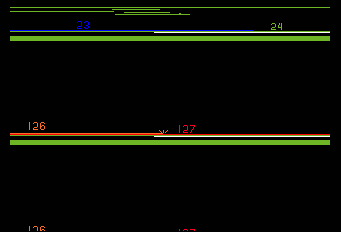 Please note that I've tried 240, 256, 320 and 336 wide screen modes and the safe timing is different for each one. Here's the code that I've come up with, which works (in mednafen) for all of those screen modes ... (please note that I'm using Daimakaimura's VDC settings for it's 320 wide mode here) (please also note that it's safe to set the VDC's CR register a little earlier than the BYR/BXR registers) (finally ... please note that this definitely needs to be tested on a real PCE CD-ROM!!!)
; PCEAS/HuC include files.

                .list

                include "macro.inc"
                include "equ.inc"
                include "vdc.inc"
                include "system.inc"

;
; PCEAS sets up the following values in the IPL ...
;
; Program load address : $4000
; Program exec address : $4070
; MPR2 (Bank @ $4000)  : $80
; MPR3 (Bank @ $6000)  : $81
; MPR4 (Bank @ $8000)  : $82
; MPR5 (Bank @ $A000)  : $83
; MPR6 (Bank @ $C000)  : $80
;

REDLINE         = 127
GREENLINE       = 24

                .zp
                .bss
                .org    $2680

                .code
                .bank   0

                .org    $4000

                ds      $70

                .org    $4070

boot:           jsr     ex_dspoff
                jsr     ex_vsync

                lda	#1
                ldx     #40
                ldy     #28
                jsr     ex_scrmod

                vreg    #10
                stw     #$0503,video_data
                vreg    #11
                stw     #$0627,video_data

                lda     #%001
                jsr     ex_scrsiz

                vreg    #0
                stw     #0,video_data
                vreg    #2
                tia     graphics,video_data,(graphics_end - graphics)

                stw     #palettes,bgc_ptr
                stb     #(graphics - palettes)/32,bgc_len
                stw     #palettes,sprc_ptr
                stb     #(graphics - palettes)/32,sprc_len
                stb     #2,color_cmd
.wait:          lda     color_cmd
                bne     .wait

                lda     #<(REDLINE+64)
                ldx     #>(REDLINE+64)
                jsr     ex_setrcr

                php
                sei
                stw     #my_vsync,vsync_hook
                stw     #my_hsync,hsync_hook
                plp
                lda     #%11110000                      ; enable new handlers
                tsb     <irq_m                          ; disable BIOS code

                jsr     ex_vsync

                ;

.hang:          jsr     ex_vsync
                bra     .hang

;
; Ugly replacement for the System Card's VSYNC handler.
;

my_vsync:       st0     #5
                st1     #$CC                            ; BG on, SPR on, VBL on, RCR on

                st0     #8
                st1     #<0
                st2     #>0

                jsr     ex_joysns
                rts

;
; This code is entered 68 cycles after the System Card's IRQ1 handler begins executing.
;
; If we burn another 34 cycles before setting BYR, then we're OK in 240, 256, 320 and 336
; screen modes. NOTE ... set BYR before BXR!!!
;

my_hsync:       lda     #4                              ; 24 cycle delay.
.wait:          dec     a
                bne     .wait

                st0     #5                              ; 10 cycles to set CR
                st1     #$CC                            ; BG on, SPR on, VBL on, RCR on

                ; This is now 102 cycles after the IRQ1 handler starts executing.

                st0     #8
                st1     #<(GREENLINE-1)
                st2     #>(GREENLINE-1)
                rts

;
;
;

palettes:       incbin  "C8HVuld.pal"
graphics:       incbin  "C8HVuld.bat"
                incbin  "C8HVuld.chr"
graphics_end:
|
|
touko
Punkic Cyborg
Posts: 106
|
Post by touko on Jul 20, 2018 7:18:24 GMT
Hum, you can doing this but it bypasses entirely the bios's irq1 handler and some bios functions will not work anymore or not correctly,frankly it's a bad idea to do like this,unless you know what you are doing.
Use only the vsync_hook and hsync_hook, they were planned for that purpose without breaking all the system functions.
Why the use of a delay in your hsync ?
BTW elmer's code seems correct,except after seting the vsync/hsync hook, he's not enabling interrupts with cli(maybe not useful here)..
I think this:
lda     #%11110000                      ; enable new handlers

tsb     <irq_m                          ; disable BIOS code
Must be replaced by:
lda     #%01010000                      ; enable new handlers

tsb     <irq_m                          ; disable BIOS code
It's just my opinion,but it enables only the user vsync/hsync functions .
If i can give you an advice punch, for testing your irq handler, it's more easy to change only the color of the desired scanline to be sure it works correctly rather than testing directly with the Vscroll .
|
|
Deleted
Deleted Member
Posts: 0
|
Post by Deleted on Jul 20, 2018 17:12:40 GMT
The delay did it for me, but do you really have to keep writing register #5 every interrupt? I'm getting some NES flashbacks here  some bios functions will not work anymore or not correctly,frankly it's a bad idea to do like this,unless you know what you are doing. which functions? I'll only be mad if CD_READ stops working. |
|
|
|
Post by elmer on Jul 20, 2018 18:07:16 GMT
Why the use of a delay in your hsync ? Please read what I've written earlier in the thread, try to understand it, and then imagine what happens when the RCR interrupt is triggered just after the CPU starts executing a transfer instruction such as ... tia my_graphics, video_data, 32The delay is needed in order to guarantee stable operation when using tia (or other transfer) instructions in the main code. Run it yourself and see ... rcr_split.rarBTW elmer's code seems correct,except after seting the vsync/hsync hook, he's not enabling interrupts with cli(maybe not useful here).. It's correct, it is a choice. That's because the System Card starts the user program with interrupts enabled, and I chose to demonstrate the use of the php, sei, plp sequence for re-entrant irq-safe coding. If i can give you an advice punch, for testing your irq handler, it's more easy to change only the color of the desired scanline to be sure it works correctly rather than testing directly with the Vscroll . Nope, absolutely not. The whole point is that there are timing-dependant issues with setting the scroll registers. lda #%01010000 ; enable new handlers
tsb <irq_m ; disable BIOS codeIt's just my opinion,but it enables only the user vsync/hsync functions . No. That still leaves the System Card setting the scroll registers during an RCR interrupt. It's better to handle that yourself so that you can enable/disable sprites as well (if needed), and also set up a subsequent RCR interrupt. Even HuC agrees ... it uses %11110000 so that it can handle both vsync and hsync without undue interference. But there's little reason to use %00000010 and take over the whole IRQ1 processing. Now, you can if you wish, and it doesn't break much at all, and it's very easy to copy the few calls that the System Card's routine makes and have everything work normally. Hum, you can doing this but it bypasses entirely the bios's irq1 handler and some bios functions will not work anymore or not correctly,frankly it's a bad idea to do like this,unless you know what you are doing. Use only the vsync_hook and hsync_hook, they were planned for that purpose without breaking all the system functions. Yep, you should definitely know what you're doing before you mess with things, and like you, I would recommend folks to just use the vsync_hook and hsync_hook. But it is a really simple system, and I think that any assembly language programmer would be advised to understand what goes on in there. delay:
e866: 60 RTS
hsync_hook:
e867: 6c 0a 22 JMP ($220a)
vsync_hook:
e86a: 6c 08 22 JMP ($2208)
irq1_hook:
e86d: 6c 02 22 JMP ($2202)
IRQ1:
e870: 9f f5 fa BBS1 <irq_m, irq1_hook
e873: 48 PHA
e874: da PHX
e875: 5a PHY
e876: ad 00 00 LDA video_reg
e879: 85 f6 STA <vdc_sr
e87b: 5f f6 3b BBR5 <vdc_sr, $e8b9
; VSYNC
e87e: 03 05 ST0 #$05
e880: a5 f3 LDA <vdc_crl
e882: 8d 02 00 STA video_data_l
e885: a5 f4 LDA <vdc_crh
e887: 8d 03 00 STA video_data_h
e88a: ee 41 22 INC irq_cnt
e88d: df f5 24 BBS5 <irq_m, $e8b4
e890: 03 07 ST0 #$07
e892: 73 0c 22 02 00 02 00 TII bg_x1, video_data, $0002
e899: 03 08 ST0 #$08
e89b: 73 10 22 02 00 02 00 TII bg_y1, video_data, $0002
e8a2: 20 09 e5 JSR ex_colorcmd
e8a5: ee 49 22 INC rndseed
e8a8: a5 e7 LDA <psg_driver_mode
e8aa: c9 01 CMP #$01
e8ac: d0 03 BNE $e8b1
e8ae: 20 cf e6 JSR psg_driver_update
e8b1: 20 9a e4 JSR ex_joysns
e8b4: 4f f5 02 BBR4 <irq_m, $e8b9
e8b7: 44 b1 BSR vsync_hook
; END OF VSYNC HANDLER
e8b9: 2f f6 1e BBR2 <vdc_sr, $e8da
; HSYNC
e8bc: ff f5 16 BBS7 <irq_m, $e8d5
e8bf: 44 a5 BSR delay
e8c1: 44 a3 BSR delay
e8c3: 03 07 ST0 #$07
e8c5: 73 0e 22 02 00 02 00 TII bg_x2, video_data, $0002
e8cc: 03 08 ST0 #$08
e8ce: 73 12 22 02 00 02 00 TII bg_y2, video_data, $0002
e8d5: 6f f5 02 BBR6 <irq_m, $e8da
e8d8: 44 8d BSR hsync_hook
; END OF HSYNC HANDLER
; END OF IRQ1
e8da: a5 f7 LDA <vdc_reg
e8dc: 8d 00 00 STA video_reg
e8df: 7a PLY
e8e0: fa PLX
e8e1: 68 PLA
e8e2: 40 RTI
|
|
touko
Punkic Cyborg
Posts: 106
|
Post by touko on Jul 20, 2018 18:24:53 GMT
You are right, it's because i watched my irq handler for hucard(it enables only 2 bits), but for cdrom you must enable those 4 bits .
I agree or call the bios vsync handler at the end of your for exemple, it works too (already done),but a bit dirty .
|
|
|
|
Post by elmer on Jul 20, 2018 18:45:22 GMT
The delay did it for me, but do you really have to keep writing register #5 every interrupt? I'm getting some NES flashbacks here No, you don't need to set it ... but, at some point, you'll probably find that you want to set it, and it's useful to show that you only need to write the low byte, and that you can do it earlier than it is safe to write the scroll registers (because it gets shadowed earlier on the scanline, right at the beginning of the HDS period). It is particularly useful to have the capability to enable/disable sprites during the RCR interrupt, so that you can display status panels at the top or bottom of the screen, and not worry about sprites overlapping them. |
|
Deleted
Deleted Member
Posts: 0
|
Post by Deleted on Jul 22, 2018 16:29:46 GMT
Thank you all, this thread was most informative. ^^
|
|


 that's not the issue I was having. Guess I have to improve my communication skills.


