|
|
Post by digipiggy on May 24, 2019 15:53:59 GMT
|
|
exodus
Punkic Cyborg

Posts: 161
|
Post by exodus on May 24, 2019 17:53:47 GMT
that thing looks like it'd snap right off!
|
|
|
|
Post by gredler on May 24, 2019 17:59:43 GMT
I'd break that thing off for sure, in all meaning of the phrase  |
|
majors
Punkic Cyborg
Have cabs, will travel
Posts: 158
Fave PCE Shooter: Parodius
Fave PCE Platformer: Legendary Axe
Fave PCE Game Overall: Spriggian
Fave PCE RPG: Ys
|
Post by majors on May 28, 2019 21:32:30 GMT
Aw, you know there is some 3d printer file for it...all the cool kids 3d print.
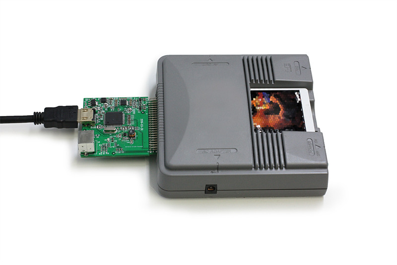
Doesn't do me much good in my current setup, but for those that do not have PVM's(nor the space or $$), this could be a quick and easy solution with HDMI. Of course, no CD function. This retro RGB/upscale/videophile trend is a rabbit hole.
|
|
keithcourage
Punkic Cyborg
https://www.facebook.com/turbografxfan/
Posts: 231
|
Post by keithcourage on May 29, 2019 10:36:45 GMT
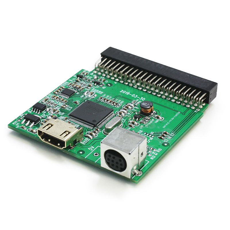
I hope this uses the RGB signals. The chip on the board looks like the ones used in those pound/hyperkin HDMI cables. So most likely the quality will be comparable.
|
|
|
|
Post by dshadoff on May 29, 2019 10:52:12 GMT
I don't know about that. Looking at that picture of the board, it looks like the board grabs the signal lines for R,G,B, and passes them through some sort of passive (capacitor or resistor - can't tell), and feeds them to an unpopulated IC footprint on the board. This is not a good sign for RGB.
Of course this picture is probably not fully representative of the final product, but this is just what I can see from the picture.
|
|
|
|
Post by soop on May 29, 2019 10:52:25 GMT
I hope this uses the RGB signals. The chip on the board looks like the ones used in those pound/hyperkin HDMI cables. So most likely the quality will be comparable. I'm 90% sure those traces you see on the far right are going to the three RGB outputs (I always forget which side they come from). So I think it's likely the DIN socket outputs RGB. Can't say that the HDMI will. |
|
|
|
Post by Black_Tiger on May 29, 2019 14:11:19 GMT
It's supposed to just work with the stock composite signal. Even if it does any upscaling, it's not worth using over an external composite-to-hdmi device.
|
|
|
|
Post by soop on May 30, 2019 10:46:32 GMT
It's supposed to just work with the stock composite signal. Even if it does any upscaling, it's not worth using over an external composite-to-hdmi device. Ok, it *definitely* taps the RGB output. I had a quick look and confirmed those traces. The odd thing is, is looks like it also taps composite but not sync, so I have no idea how that's supposed to work. I mean I could be wrong, it is hard to follow the outputs from the core unit, but at least I can tell you that this thing is tapping RGB for at least one output. |
|
|
|
Post by dshadoff on May 30, 2019 12:07:41 GMT
It's supposed to just work with the stock composite signal. Even if it does any upscaling, it's not worth using over an external composite-to-hdmi device. Ok, it *definitely* taps the RGB output. I had a quick look and confirmed those traces. The odd thing is, is looks like it also taps composite but not sync, so I have no idea how that's supposed to work. I mean I could be wrong, it is hard to follow the outputs from the core unit, but at least I can tell you that this thing is tapping RGB for at least one output. I see the traces leading to C5, C6, and C7... but that whole section of the board after that point is unpopulated... where do you see these lines going ? good news is that it was designed to use RGB, but bad news is they decided to give up on it for some reason.... |
|
|
|
Post by soop on May 30, 2019 12:38:58 GMT
Ok, it *definitely* taps the RGB output. I had a quick look and confirmed those traces. The odd thing is, is looks like it also taps composite but not sync, so I have no idea how that's supposed to work. I mean I could be wrong, it is hard to follow the outputs from the core unit, but at least I can tell you that this thing is tapping RGB for at least one output. I see the traces leading to C5, C6, and C7... but that whole section of the board after that point is unpopulated... where do you see these lines going ? good news is that it was designed to use RGB, but bad news is they decided to give up on it for some reason.... you're right... on further inspection of the bottom picture, it looks like there's a missing package that the traces would have led to. Maybe a THS7314 or something. But without that, the amplifier part can't work. So it looks like this thing isn't as useful as I thought. I wonder why they got that far and then just gave up? |
|
|
|
Post by dshadoff on May 30, 2019 19:18:24 GMT
I figure one of:
1) It wasn’t much better quality than composite.
2) They didn’t want to deal with the furor that SSD3 did.
3) Maybe the cost of the additional parts wasn’t considered “worth it”... but this implies that they could come back with a special edition...
But really, who knows for certain...
|
|
|
|
Post by dshadoff on Sept 28, 2019 13:10:46 GMT
I had been watching this item on Amazon.co.jp, to see whether it would be interesting or not. Sometimes you'll see comments and so on.
It became available on September 24, and now (as of September 28), the listing has been completely removed - not just sold out, but the page and listing are gone.
It had been listed under ASIN B07S2PGZY2 .
I suppose... we draw our own conclusions.
|
|